
I2C: part 2
Introduction
In the previous tutorial, we learned about the I2C Communication. Also, we introduced two components and learned how to communicate with them. To understand the I2C communication better, let’s work with another component and define an Arduino as a slave.
Temperature: DS1621
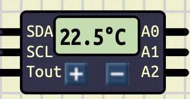
DS1621 is a component that measures the temperature. It can measure temperatures between $[-55C, 125C]$ with the resolution of $0.5$. It uses I2C communication to report its data. We can access this component in SimulIDE at: Micro/Sensors/DS1621. Here is how it looks like in SimulIDE:
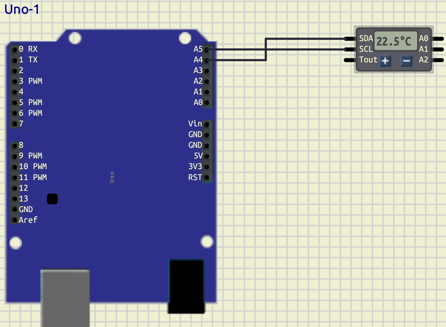
Now, let’s connect that to an Arduino. Here how it should look like:
At first, let’s find out its id with the scanning code that we wrote
in the previous tutorial.
After running that code, we would get 0x48 as its address.
Let’s store it in a definition like below:
#define DS1621_ADDRESS 0x48
Advance note: we can change the slave address of this component using
A0,A1, andA2pins. It is useful when we want to connect multiple DS1621 at once.
Working with DS1621, like the other components, has its own standard which we should apply it in order for it to work. Let’s learn the necessary things that we should do for a successful communication step by step. First, let’s take a look at its command table below:
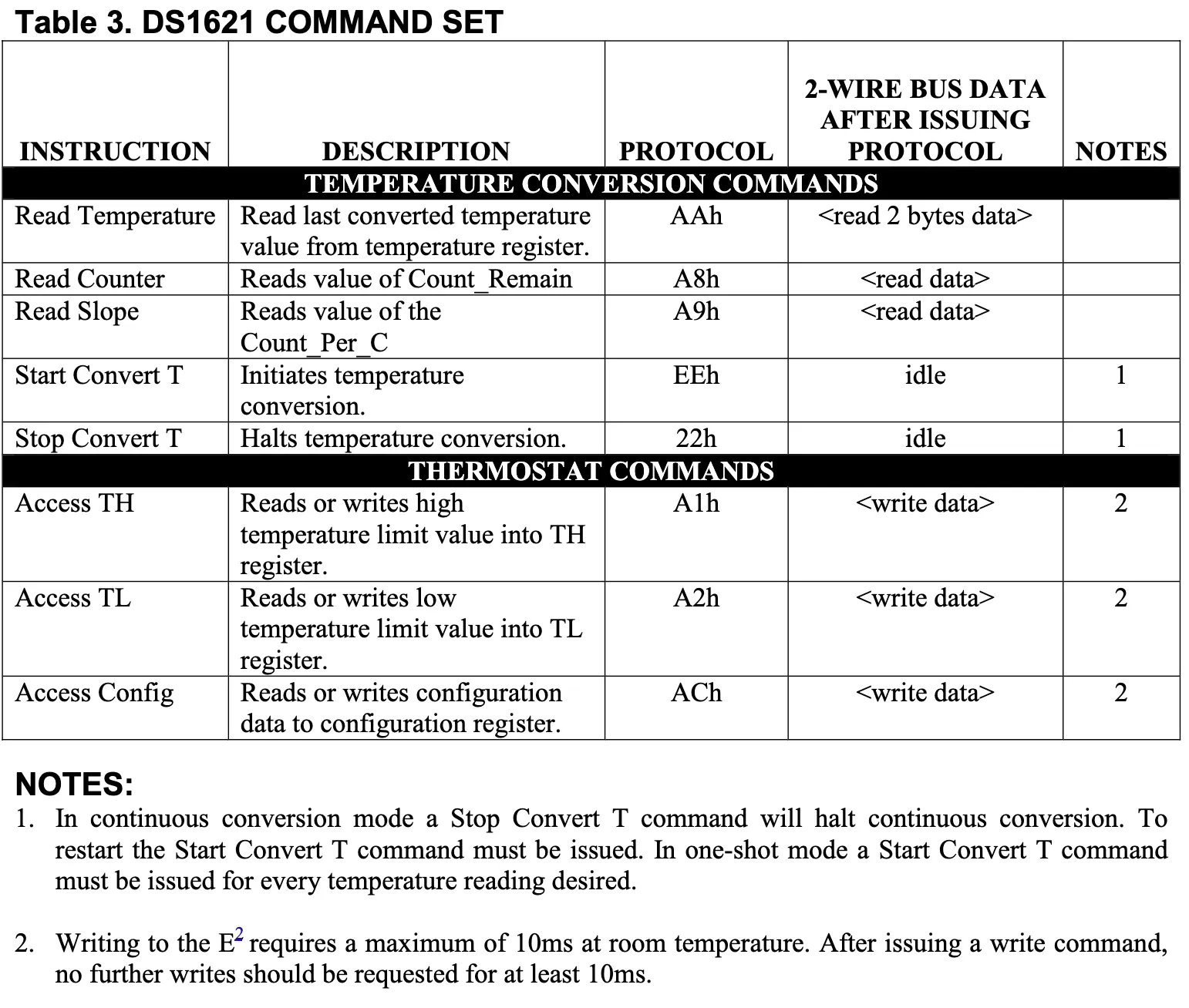
In this tutorial, we only need some of its commands to read data
from this component.
At first, we should initialize our conversation.
As you can see in the table, the conversation initialization
is on the Start Convert T row, with the protocol of EEh.
So, at the setup function we should set that.
Here is the code that we can use.
Wire.beginTransmission(DS1621_ADDRESS);
Wire.write(0xEE);
Wire.endTransmission();
For the next step, we should take a look at its config register. You can see that in the figure below.

As you can see, at the lowest bit of its register, there is a
bit called 1SHOT.
When this bit is set to 1, it only returns the temperature one time
and closes the conversation.
But, we don’t want that to happen.
We want to continuously get data from it.
So, we should set that bit to 0.
In order to do so, first, we should access config.
As you can see in the command table, its protocol is ACh.
Then we are able to change the config in a way that we want.
Here is the code that we can use in our setup function:
Wire.beginTransmission(DS1621_ADDRESS);
Wire.write(0xAC); // access config
Wire.write(0x00); // put `0` in all the bits of the config register
Wire.endTransmission();
As you can see, in the code above, we at first, requested to access the config.
Then we put 0 for all the bits of the config register.
Now, we can make sure that 1SHOT is set to 0 and the communication
would not be interrupted after one time of reading data.
Now, it’s time to learn how the data is being stored in the DS1621.
The table below, has explained it using example.
Let’s take a look at it.
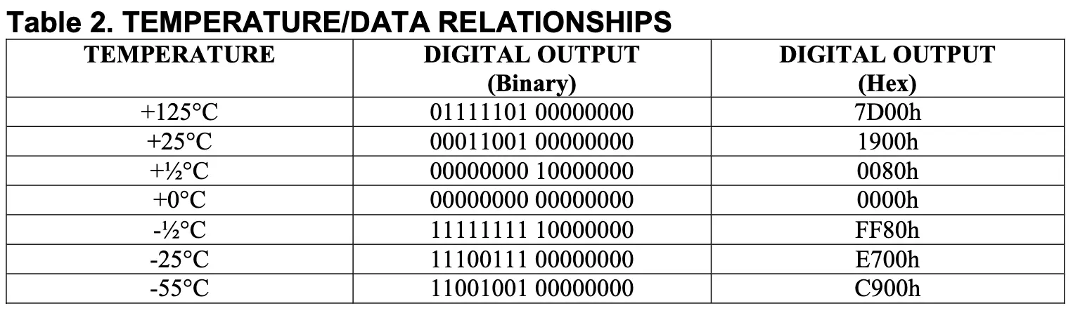
As you can see, each temperature consists of 2 bytes.
The highest value byte has the integer part of the temperature.
And in the lowest value byte the decimal part is stored.
But they resolution of the DS1621 is only $0.5$.
So, to show that, they use the highest bit of it.
If it’s set to 1 it is equal to $0.5$ and if it has the value of
0, it is equal to $0.0$.
With knowing that, let’s start writing a function to read the temperature.
float read_temperature()
{
  Wire.beginTransmission(DS1621_ADDRESS);
  Wire.write(0xAA);
  Wire.endTransmission();

  Wire.requestFrom(DS1621_ADDRESS, 2);
  byte temp_msb = Wire.read();
  byte temp_lsb = Wire.read();

  float result = temp_msb;
  if (temp_lsb & 0x80)
  {
    result += 0.5;
  }
  return result;
}
As you can see, in the function above, at first, we requested that
we want to read the temperature.
If you look at the table, it is in the first row with the protocol of AAh.
Then, we should request 2 bytes from the component.
We use the highest value byte as it is.
But for the lowest value byte, we should check if the highest bit is set
to one or not.
If it is set to 1, then we should add 0.5 to our result.
Now, let’s read the temperature every 1 seconds, and display it in the
serial terminal.
Here is the full code:
#include <Arduino.h>
#include <Wire.h>

#define DS1621_ADDRESS 0x48

float read_temperature()
{
  Wire.beginTransmission(DS1621_ADDRESS);
  Wire.write(0xAA);
  Wire.endTransmission();

  Wire.requestFrom(DS1621_ADDRESS, 2);
  byte temp_msb = Wire.read();
  byte temp_lsb = Wire.read();

  float result = temp_msb;
  if (temp_lsb & 0x80)
  {
    result += 0.5;
  }
  return result;
}

void setup()
{
  Serial.begin(9600);
  Wire.begin();

  for (int i = 0; i < 128; i++)
  {
    Wire.beginTransmission(i);
    if (Wire.endTransmission() == 0)
    {
      Serial.println("Device found at address: 0x" + String(i, HEX));
    }
  }

  Wire.beginTransmission(DS1621_ADDRESS);
  Wire.write(0xEE);
  Wire.endTransmission();

  Wire.beginTransmission(DS1621_ADDRESS);
  Wire.write(0xAC);
  Wire.write(0x00);
  Wire.endTransmission();

  delay(200);
}

void loop()
{
  float temperature = read_temperature();

  Serial.println(String(temperature) + " C");

  delay(1000);
}
Your output should look like below:
As you can see, in the output above, when we change the temperature, the number displayed in the serial terminal would change accordingly.
Arduino as an I2C Slave
Now, to understand the I2C communication better, let’s learn how to set up an Arduino as a slave. At first, let’s connect another Arduino Uno to our current setup. The connection should look like this:
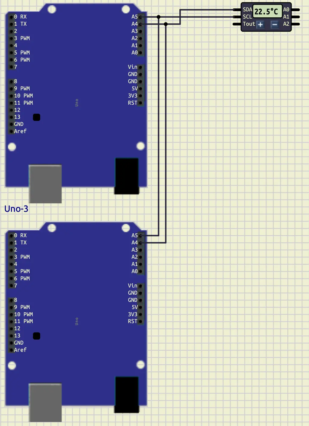
As you can see A4 is connected to A4 (SDA) and A5 (SCL) of the both
are connected together.
Now, it’s time to set up our Arduino as a slave.
To do so, at first we need a separate project for our second Arduino.
Then, we need to set up Wire with the address that we want to give that
Arduino to be able to call it.
We can do this like below:
Wire.begin(8);
In the code above, we set the address to 8.
We should remember that address anytime that we want to call
the second Arduino.
As you can recall, we have two modes when we want to start a communication with a slave. We can write to a slave, or we can read from it. Now, let’s implement both of the modes, starting from writing to it.
When we write on a slave, that slave should receive that data.
To say, what to do when you are receiving data, we should define
a function and pass it to Wire.
Here is how we can use it.
Wire.onReceive(receiveEvent);
On the code above, when we receive a data, a function called receiveEvent
would be called.
This calling would work like an Interrupt, so we can sure
we don’t miss the data when we receive it.
Now, let’s implement that function.
String result;
bool i2c_ready = false;

void receiveEvent(int howMany)
{
  i2c_ready = true;
  result = "";
  while (Wire.available())
  {
    char c = Wire.read();
    result += c;
  }
}
The code above, is one of the ways that we can use to implement that function.
As you can see, we have two global variables called result and i2c_ready.
result stores the data received and i2c_ready sets to true when there
is data.
For the receiveEvent function, we should have an argument.
This argument contains the number of the bytes sent to the slave from the master.
Anytime that this function is called, we set i2c_ready to true and remove
the previous data.
Then we read all the bytes and add them to result until the communication is closed.
Now, let’s write the data received in the slave Arduino to the serial
terminal in our loop function.
Here is the code that can achieve that.
if (i2c_ready)
{
  i2c_ready = false;
  Serial.println(result);
}
In the code above, we check i2c_ready to see if there is any data received or not.
If there was any, we set i2c_ready to false and print that data.
Now, let’s send data from the master Arduino to see if we can catch it in our slave. To do so, we can use a code like this:
#define ARDUINO_2 0x08
String str_temp = String(temperature);

Wire.beginTransmission(ARDUINO_2);
for (unsigned int i = 0; i < str_temp.length(); i++)
{
  Wire.write(str_temp[i]);
}
Wire.endTransmission();
First, we add a definition with the value of 0x08 (Arduino slave address that we set)
called ARDUINO_2.
Then, after reading the temperature, we cast it into String.
Then we start a transmission with our second Arduino and
send all the bytes of that string to it.
And finally we close the transmission.
Here is the output:
Now, let’s learn how to request read from slave.
To handle the request, we can use a function called onRequest.
This function gets called when we master wants to read data
from the slave.
Here is an example of how we can use it:
Wire.onRequest(requestEvent);
As you can see, in the code above, we have a function called requestEvent
which we are going to implement it later.
We pass that function to Wire.onRequest.
Now, let’s implement requestEvent in a way that it has 5 as its
first byte and 6 as its second byte.
Here is the code for that.
void requestEvent()
{
    Wire.write(5);
    Wire.write(6);
}
Now, let’s go to our master and request two bytes. Here would be the code for that.
Wire.requestFrom(ARDUINO_2, 2);
String received_data = "";
received_data += Wire.read();
received_data += Wire.read();

Serial.println("Received from Arduino 2: " + received_data);
As you can see, in the code above, we have read 2 bytes
and add them to a string called received_data.
Then, we display this variable into Serial Terminal.
Before running that code, we should say an important implementation
detail in Wire.
In Wire, onReceive function gets triggered in both sending and receiving
data.
To prevent the code in the function from executing when it is not needed
to be executed, we can do something like this at the start of the function.
if (howMany == 0)
    return;
As you can see, in the code above, we checked if the master wants any bytes
or not.
If it didn’t need any bytes (howMany == 0), we would put a return.
This helps us not to execute the rest of the codes in that function.
The output would look like this:
Conclusion
In this tutorial, we dived deeper in I2C communication.
At first, we learned about another component called DS1621.
This component would measure the temperature.
Then, we have learned how to set up an Arduino to be an slave in
serial communication.