I2C: part 1
Introduction
In the previous Tutorial, we learned about Interrupt. In this tutorial we will learn about I2C communication.
I2C Communication
Inter-Integrated Circuit (I2C), is a two-wire communication protocol. This protocol is designed for short-distance communication between microcontrollers and peripherals. It uses two pins to set up the communication:
- SDA: Serial Data
- SCL: Serial Clock
This way of communication, allows us to connect more than 1 component to the same 2 pins.
For I2C every component has its own address.
These addresses are mostly 7-bit.
I2C is a master and slave protocol. It means that one device (Our Arduino) is a master, and the other devices are slaves. A master device controls the clock created in SCL. Also, master decides that if it wants to communicate with a slave or not. Each message of master is like below:
| Field | Bit Count | Description |
|---|---|---|
| START | — | SDA goes LOW while SCL is HIGH → begins communication |
| Slave Address | 7 bits | Unique address of target device (0–127) |
| R/W Bit | 1 bit | 0 = Write, 1 = Read |
| ACK/NACK | 1 bit | Receiver pulls SDA LOW to acknowledge (ACK), HIGH for no-ack (NACK) |
| Data Byte 1 | 8 bits | First byte of data to write or read |
| ACK/NACK | 1 bit | Receiver acknowledges the byte |
| Data Byte 2…N | 8 bits | Additional data bytes (optional, depends on protocol) |
| ACK/NACK | 1 bit | Acknowledge after each data byte |
| STOP | — | SDA goes HIGH while SCL is HIGH → ends communication |
In the table above, you can see the message structure in I2C.
First, master puts the SDA to low.
This indicates that all slaves should listen.
After that, it tells which slave address it wants to talk to.
Then, with 1 bit tells the slave if it wants to read or write.
Next, there would be an acknowledgement bit.
If slave was available, it would set the acknowledgement bit to 0.
(The default value of SDA is always 1).
After that, there would be a byte of data.
Respect to the mode (read or write), master can send or receive that byte.
Then, whoever receives the data, should set the acknowledgement bit to 0.
These byte transfer and acknowledgement can be repeated multiple times, until a stop signal.
Stop signal can be created when we put the SDA to 1.
To have a I2C communication in Arduino uno, we should use these pins:
| signal | pin |
|---|---|
| SDA | A4 |
| SCL | A5 |
Wire
To control the I2C communication, Arduino has a library called Wire.
We can include Wire in our code like below:
#include <Wire.h>
To set up the I2C communication, we can use .begin() function, like below:
Wire.begin();
After doing that, we can start a communication with a slave in two ways:
- write
- read
To start a communication with a slave in order to write, we can use the code below:
Wire.beginTransmission(addr);   // start the communication in order to write with the slave with the address of `addr`
Wire.write(data);               // write data
Wire.endTransmission();         // finish transmission
If we want to our communication to be a read communication, we can
Wire.requestFrom(addr, number); // start a read communication with the slave with the address of `addr` and read `number` bytes
Wire.read();                    // read bytes
Let’s connect an I2C component to the Arduino and check these functions.
Finding I2C address
Now, let’s connect an I2C component to an Arduino and find its I2C address. For the I2C component, we choose a clock called DS1307 (Micro/Peripherals/DS1307). Let’s connect its SCL pin to A5 and SDA to A4.
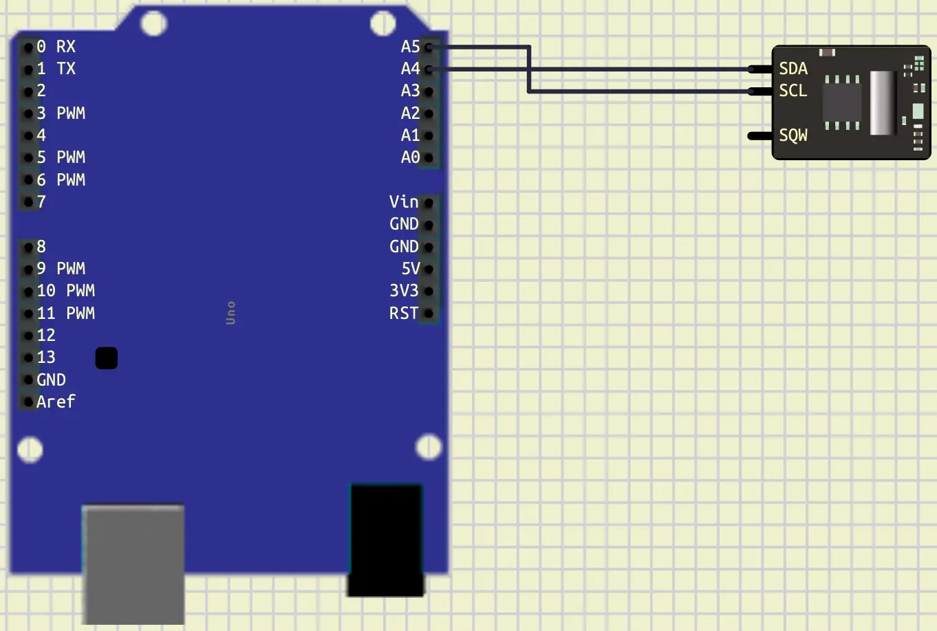
Your connection should look like the figure above. Now, let’s write a code to find the address of this clock.
#include <Arduino.h>
#include <Wire.h>

void setup()
{
  Wire.begin();
  Serial.begin(9600);
}

void loop()
{
  for (int i = 0; i < 128; i++)
  {
    Wire.beginTransmission(i);
    if (Wire.endTransmission() == 0)
    {
      Serial.println("Device found at address: 0x" + String(i, HEX));
    }
  }
  delay(2000);
}
As you can see, in the code above, we scan all the possible addresses.
We have a for loop that starts from 0 and continues until before 128.
As you recall we said that we have only 7-bits for the slave address ($2^7 = 128$).
Then we try to start communication with each id without any data transmitted.
if we could close that connection without any errors (Wire.endTransmission() == 0), it means that there is a component
connected with that id that could send the acknowledgement bit.
Then, we print that id, in a hex format, in the serial terminal.
If we only have the clock connected, the output would be 0x68.
Advance note: the 7-bit range that other components could use for the slave address is from 0x08 to 0x77. The other addresses are reserved for the I2C connection.
Clock: DS1307
The Clock that we connected in the previous section, DS1307, is called Real-time Clock (RTC) integrated circuit. This clock has a battery, and it could store and keep track of the current time and date. It has a RAM that stores the time in one byte registers. Here is the table, representing those registers with their addresses in its RAM.
| Register | Address |
|---|---|
| Seconds | 0x00 |
| Minutes | 0x01 |
| Hours | 0x02 |
| Day of Week | 0x03 |
| Day of Month | 0x04 |
| Month | 0x05 |
| Year | 0x06 |
As you can see, this table contains of seconds, minutes, hours,
Day of week (e.g. Monday=0), Day of Month, Month, and Year.
To access each of them, we can jump to the respected address and request
read from that address which we are going to learn about it.
But, at first, let’s learn how it stores each register by an example.
If it stores 0x23 it doesn’t mean $2 \times 16 + 3=35$,
it means $2 \times 10 + 3=23$.
As you might have noticed, the highest value of the hex digit is based on
10, not 16.
This is the part that we should consider when we get a register from the clock.
Now, let’s write a code to read Minutes and Hours from this clock.
#include <Arduino.h>
#include <Wire.h>

#define CLOCK_ADDRESS 0x68

void setup()
{
  Serial.begin(9600);
  Wire.begin();

  delay(1000);

  for (int i = 0; i < 128; i++)
  {
    Wire.beginTransmission(i);
    if (Wire.endTransmission() == 0)
    {
      Serial.println("Device found at address: 0x" + String(i, HEX));
    }
  }
}

void loop()
{
  Wire.beginTransmission(CLOCK_ADDRESS);
  Wire.write(0x01); // Address that we want to jump to
  Wire.endTransmission();

  Wire.requestFrom(CLOCK_ADDRESS, 2);

  byte minutes = Wire.read();
  byte hours = Wire.read();

  Serial.println("Minutes: " + String(minutes, HEX));
  Serial.println("Hours: " + String(hours, HEX));

  delay(1000);
}
As you can see, in the code above, we have read the minutes and hours registers in the clock.
In the loop function, first we started a transmission.
The first transmission, in the standard of this clock, is the address that we want to jump to.
So, we jumped at the 0x01 to access the minutes register.
After that, we requested to read 2 bytes from the clock.
We know that these bytes would represent the minutes and hours.
After our request, we should call the function read in order to read those bytes.
Your result should look like the figure below.
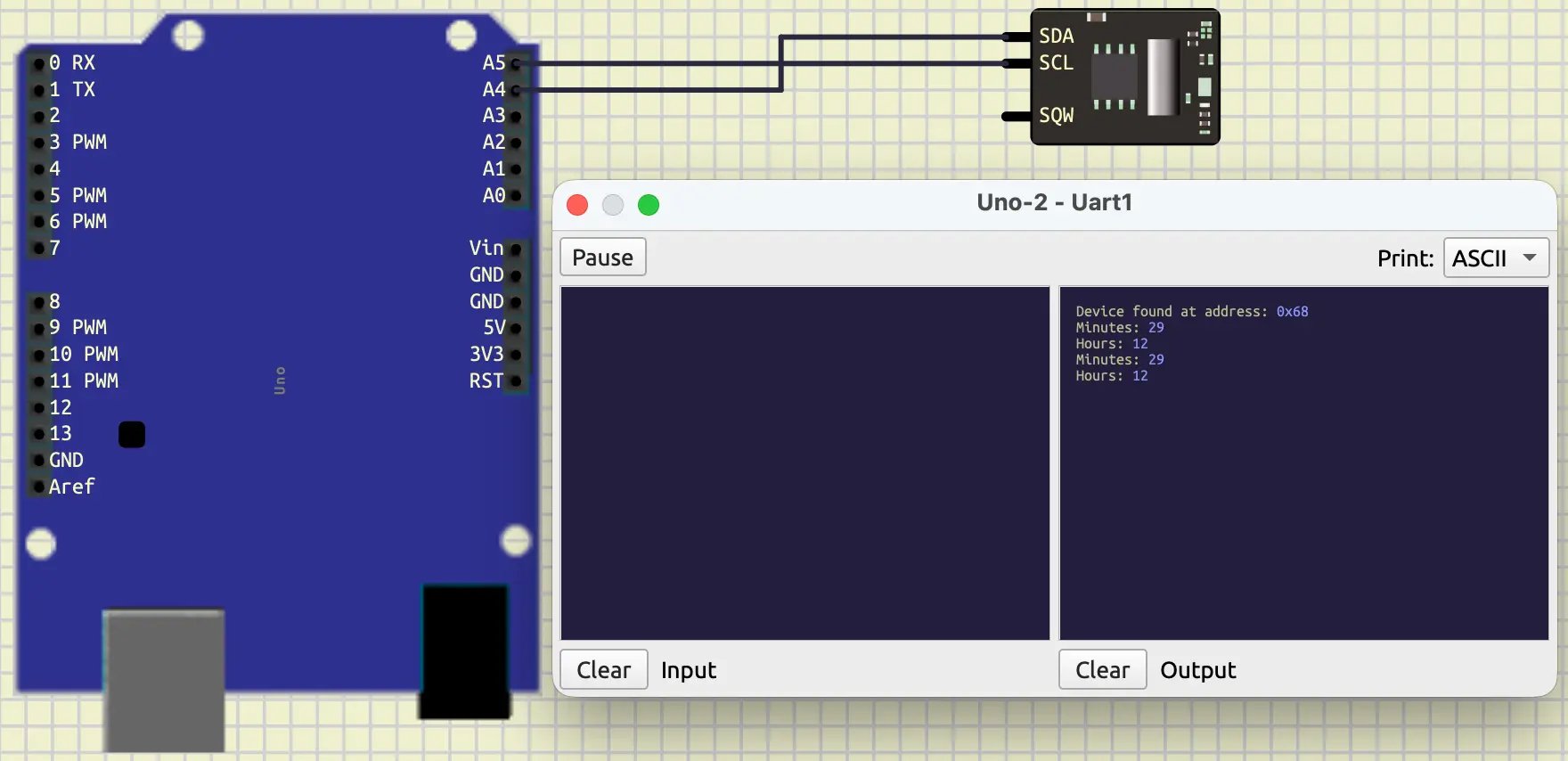
Note: it’s a good practice to keep the scanning code in the setup to make sure all the devices you are working with are connected.
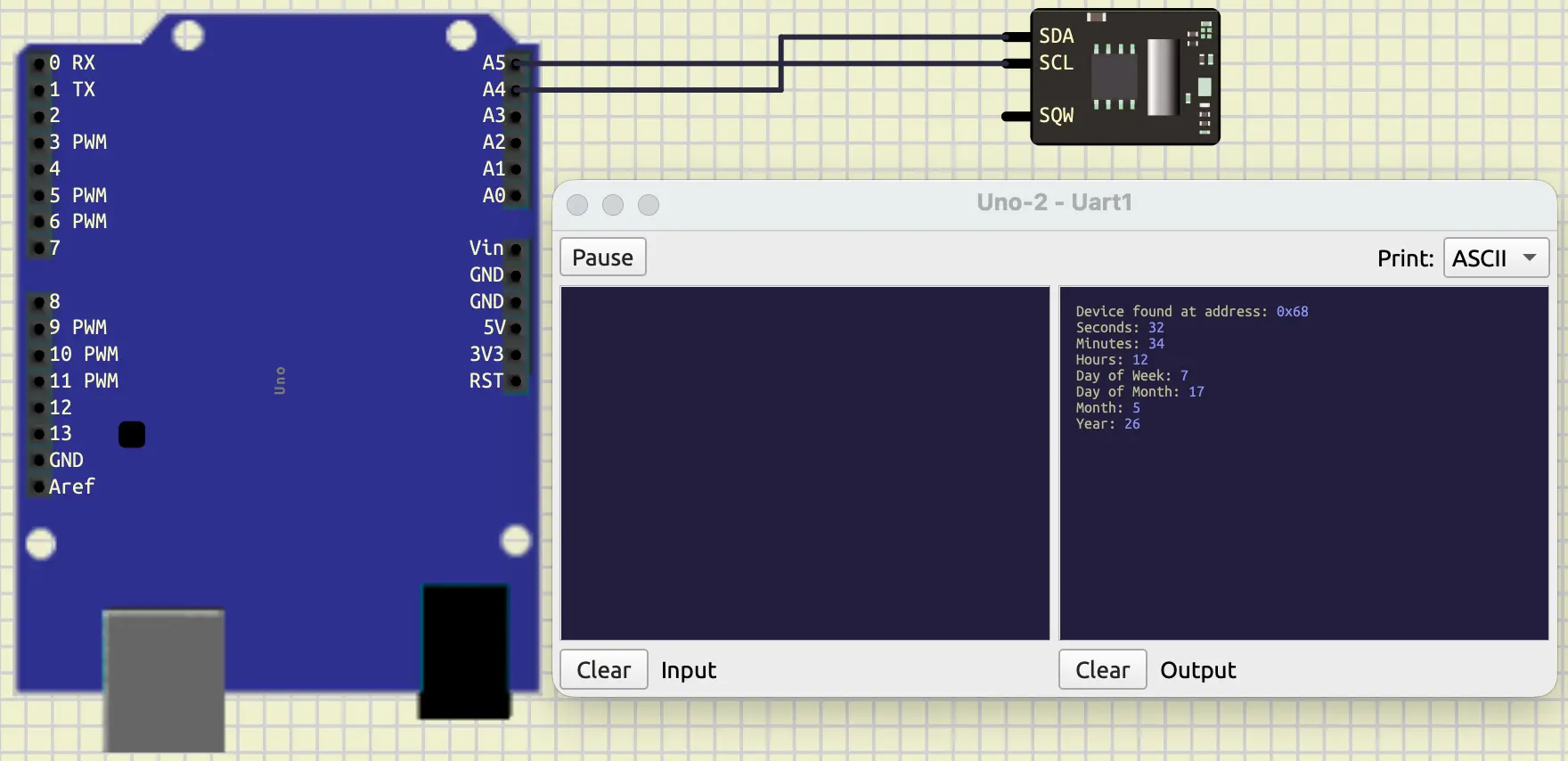
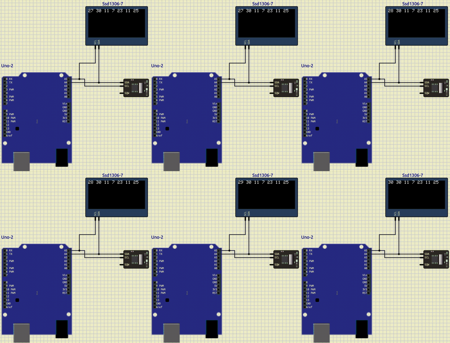
Now, read all the registers and print them in the serial terminal. Your output should look like this:
So far, we have learned how to read from the clock.
Now, let’s learn how to write data on it.
To do so, at first we should jump to the address of the register
that we want.
For example, if we want to write in the minutes register, we should jump to
0x01.
After that, we can write the data that we want.
The important thing that we should keep in our mind is how the clock
stores data.
If we have a variable with the value of 25 and tell the clock
to store it in the minutes register, it would think we mean: 0x19 (25/16=1 25%16=9).
So, to really store 25 minutes, we should convert it to 0x25.
We can do this like this: $2 \times 16+5=37=$0x25.
Here is the code that we can use:
#include <Arduino.h>
#include <Wire.h>

#define CLOCK_ADDRESS 0x68

void setup()
{
  Serial.begin(9600);
  Wire.begin();

  delay(1000);

  for (int i = 0; i < 128; i++)
  {
    Wire.beginTransmission(i);
    if (Wire.endTransmission() == 0)
    {
      Serial.println("Device found at address: 0x" + String(i, HEX));
    }
  }
}

void loop()
{
  byte minutes_to_write = 25;
  // convert 25 to 0x25
  minutes_to_write = (minutes_to_write / 10) * 16 + minutes_to_write % 10;

  // Write minutes
  Wire.beginTransmission(CLOCK_ADDRESS);
  Wire.write(0x01); // Address that we want to jump to
  Wire.write(minutes_to_write);
  Wire.endTransmission();

  // Read minutes
  Wire.beginTransmission(CLOCK_ADDRESS);
  Wire.write(0x01); // Address that we want to jump to
  Wire.endTransmission();

  Wire.requestFrom(CLOCK_ADDRESS, 1);

  byte minutes = Wire.read();

  Serial.println("Minutes:" + String(minutes, HEX));

  delay(1000);
}
As you can see, in the code above, we have applied the converting properly and then send the data to the correct register. After that, to make sure we have written a correct data, we read that register and print its value. Here is the output:
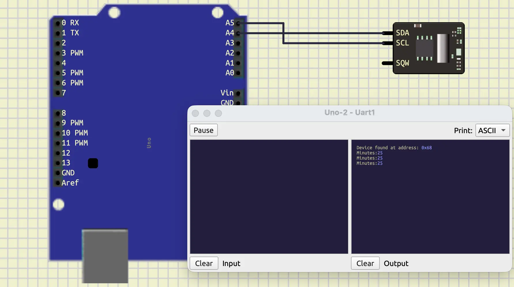
Advance note: SQW pin is short for (Square Wave Output). It is useful when we want to create an interrupt.
OLED: SSD1306
OLED (Organic Light Emitting Diode) is a graphic display module. This component is also working with the I2C communication protocol. There are different models of an OLED, the version that we are working with in this tutorial is SSD1306. You can find this component in SimulIDE at Outputs/Displays/SSD1306. Now, let’s connect this component alongside with our clock. As we already know, we should connect SCL to A5 and SDA to A4. Your connection should look like this:
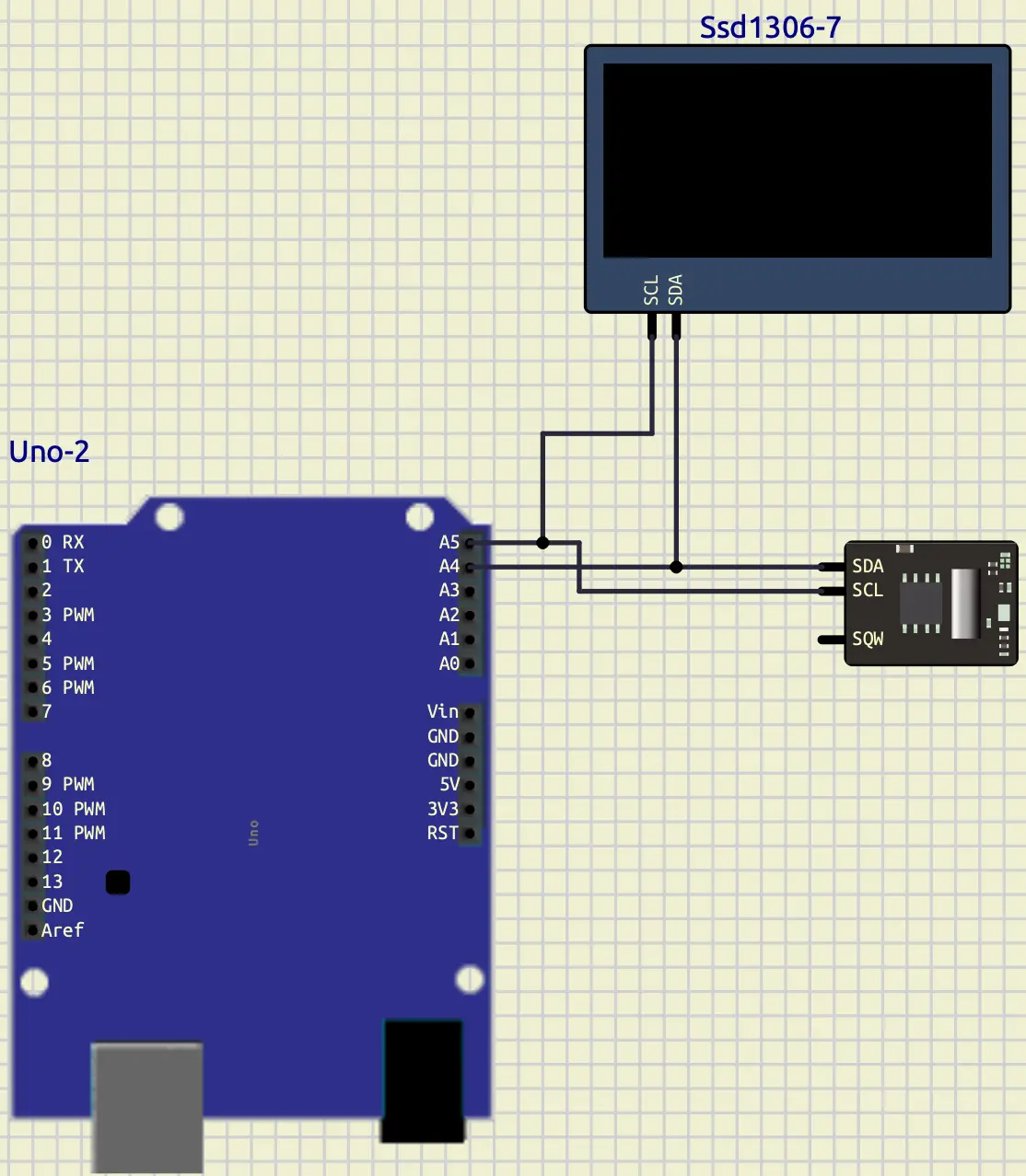
To control this component, we can use a library called Adafruit.
To add Adafruit to our project, we should add its graphic library
and a specific library designed for SSD1306.
Here is how we can do it:
lib_deps =
    Adafruit SSD1306
    Adafruit GFX Library
After that, we should include them in our code. We can do it like below:
#include <Adafruit_GFX.h>
#include <Adafruit_SSD1306.h>
Then it’s time to create an object to control our OLED display module.
#define SCREEN_WIDTH 128
#define SCREEN_HEIGHT 64

Adafruit_SSD1306 display(SCREEN_WIDTH, SCREEN_HEIGHT, &Wire);
As you can see in the code above, at first, we should define width and height of our screen, which is $128 \times 64$. Then, to initialize it we need three arguments:
- Width
- Height
- Object of the
Wire
Now, we can start our display and config it in a way that we want.
if (!display.begin(SSD1306_SWITCHCAPVCC, SSD1306_ADDRESS))
{
Serial.println("SSD1306 failed!");
for (;;)
  ;
}

display.setTextSize(1);
display.setTextColor(WHITE, BLACK);
As you can see in the code above, at first, we used begin
to set up our display.
Then, if the setup was not successful, we print that the setup is failed,
and we have an infinite loop to stop the program from continuing.
After that, we set the text size and text color.
The function setTextColor, takes two arguments, first the color
that we want to write and second the background color.
In the code above, we set the writing color to white and the background
color to black.
Like LiquidCrystal that we previously worked with,
Adafruit also has functions to write and draw things on the display.
To write something we can use the print function.
To display what we have written, we can use the function called display.
If we don’t call this function after each print, we won’t see the output
on our display.
One of the advantages and most important things about the Adafruit graphic
designer is that it works lazy.
Here by the lazy we mean, at first it gets all the things
that it has to display.
Then, when we call display, it finds the best solution to display them.
display.print();
display.display();
We also have functions to clear the display and set the cursor to the position that we want.
display.clearDisplay();
display.setCursor(0, 0);
We have so many functions that we can use, we can draw a line with drawLine,
draw a rectangle with drawRect.
You can look at the documentation or search them to learn more about them.
Also, here is a good example:
Now, print the all the registers that we get from the clock into our graphical display. Your output should look like this:
Project
Now, let’s do a project.
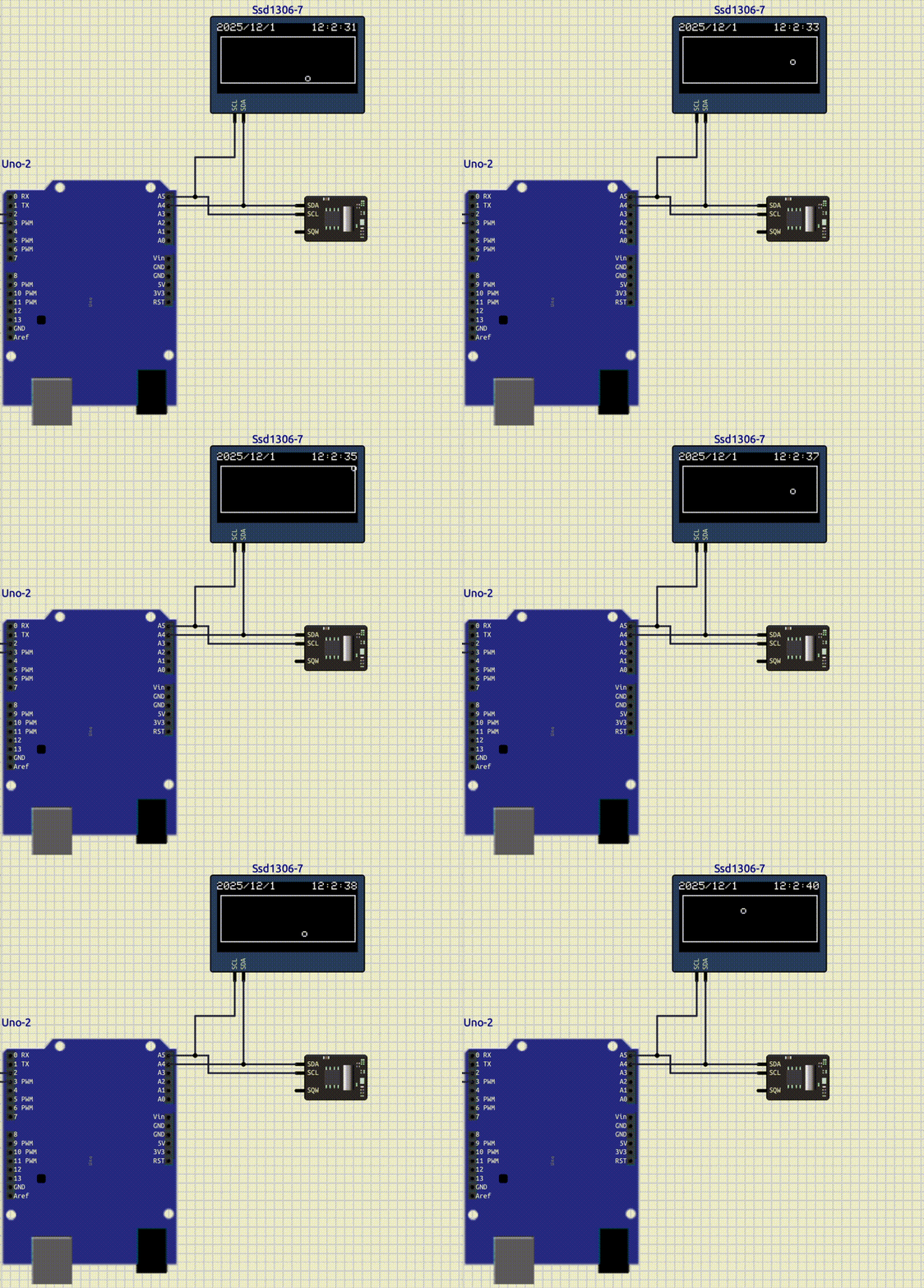
As you can see, in the figure above, we have a display and a clock connected to our Arduino. At first, we want to display the date at the first line. Then, create a border. After that, draw a circle on that border and program that ball in a way that:
- moves diagonally
- every time it hits the border, it bounces back
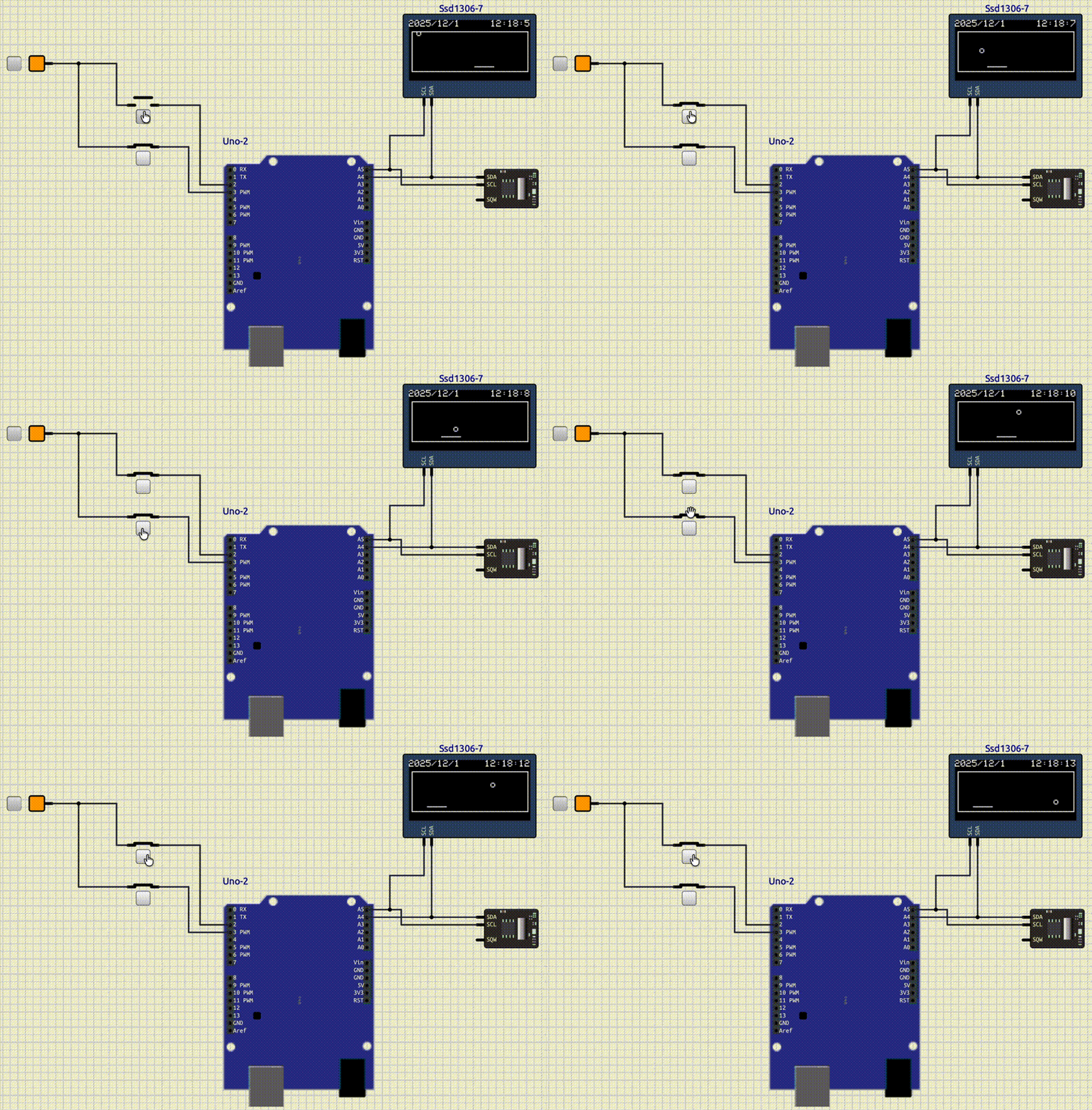
For the extra practice, you can add a line to the border and add two interrupts, like above. This line should function like:
- Every time the ball hits that line it should bounce back
- One of the interrupts should move the line left
- The other one should move the line right
- The line shouldn’t be able to go out of the border
Conclusion
In this tutorial, we have learned about I2C communication.
We explained this protocol and learned how to control it with
the Wire library.
Then, we worked with a Real Time Clock and gets the time registers from it.
After that, we introduced another component, called OLED.
We mangaed to draw shapes and write texts with this component.