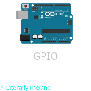
GPIO
Introduction
In the previous tutorial, we learned about the basics of Arduino. We implemented a simple Blink LED project as a Hello World. In this tutorial, we are learning more about General-Purpose Input/Output pins in Arduino.
What is GPIO?
GPIO stands for General-purpose Input/Output. There are pins in Arduino that we can determine if they should be input or output using code.
- Input pin: We read data from it.
- Output pin: We write data to it.
There are 14 Digital GPIO pins and 6 Analog GPIO pins.
In the image below, we have highlighted Digital GPIO pins with red,
and Analog GPIO pins with yellow.

To change the mode of a pin in code, we can use the function below:
pinMode(pin_number, mode);
pin_number: number of the pin that we want to change (e.g., 13)mode: we can choose the mode of the pin; two of the choices are:INPUT: 0OUTPUT: 1
In the previous tutorial, we set the mode of pin 13 to output, with the code below:
pinMode(13, OUTPUT);
If we want to change the mode of pin 3 to input, we can write a code like below:
pinMode(3, INPUT);
LED and key
Now, let’s do a project that turns on an LED whenever we press a key.
Connect an LED and a key to an Arduino
First, let’s open up SimulIDE. Then we can follow these steps to connect an LED and a key to an Arduino Uno:
- Put an Arduino Uno on the board.
- Put a fixed voltage on the board.
- Connect the fixed voltage to the reset pin of the Arduino Uno and let it be on.
- Put an LED on the board.
- Put a Resistor on the board.
- Connect the anode (tallest pin) of the LED to on pin of the Resistor.
- Connect the other pin of the Resistor to the pin 13 of Arduino Uno.
- Put a ground on the board.
- Connect the cathode (shortest pin) of the LED to the ground.
- Put a button (Switches/push) on the board.
- Put another fixed voltage on the board.
- Connect one pin of the button to the fixed voltage.
- Connect the other pin to the pin 2 of Arduino.
After the steps above, you should have something like this:

With this setup, we have pin 13 as an output pin and pin 2 as an input pin.
Write the code
Now, let’s write the code that turns the LED on and off anytime we press it. At first, we should set the mode of pin 13 to output.
pinMode(13, OUTPUT);
Next, we should set the mode of pin 2 to input.
pinMode(2, INPUT);
These codes are for initialization, so we should put them in setup() function.
Now, let’s get ready to write our logic.
We need two variables:
led_state: keeps the state of the LED (on/off).button_pressed: becomestrueif the button is pressed.
So, let’s define those variables as global variables. (below the includes)
bool led_state = false;
bool button_pressed = false;
Our logic is:
- Check if the button is pressed
- If it was pressed:
- Change the
led_state. - Write the
led_stateto output.
- Change the
So, let’s write it down.
button_pressed = digitalRead(2);
if (button_pressed)
{
    led_state = !led_state;
    digitalWrite(13, led_state);
    delay(500);
}
In the code above, we follow the logic that we have explained.
The reason that we put delay(500) is simple.
When we press the key down and release it, it takes about 200ms.
In this 200ms, button_pressed is true, so our code in the if statement would be executed many times.
To avoid this from happening, we put a delay(500).
You can see the full code here:
#include <Arduino.h>

bool led_state = false;
bool button_pressed = false;

void setup()
{
  pinMode(13, OUTPUT);
  pinMode(2, INPUT);
}

void loop()
{
  button_pressed = digitalRead(2);
  if (button_pressed)
  {
    led_state = !led_state;
    digitalWrite(13, led_state);
    delay(500);
  }
}
The output would be something like below:

Control three LEDs
Now we know how to set a pin as an input and output. Let’s add more LEDs to the board and change our program in a way that whenever we press the button, the LED that is turned on switches. Also, in our simulation, we can control the color of the LEDs. Let’s change their colors to red, yellow, and green, like a stoplight. You are free to connect the LEDs to whichever pin you want. Your output should be something like this:

Add another button
Now, let’s add another button that could disable the traffic light, and when we press it again, it would enable it again. Your output should be like this:

Conclusion
In this tutorial, we learned how to use Digital GPIO. We have introduced all the pins that you can use for Digital GPIO and how to program them in order to work correctly. We walked you through how to manage and program a simple LED and button. Then, we asked you to expand the number of LEDs to learn the Output GPIO better. Finally, we asked you to add another button to make you more comfortable with Input GPIO.
